Step Seventeen: Advanced Pacman Repair For PCB
All Ms. Pac-man boards are really Pac-man boards with new character roms, and an extra Auxiliary card with ribbon cable replacing the Z-80 CPU. The easiest way to rule out the Aux card, is to remove it and install a Z-80 on the main Pac-man main board. If the board runs fine as a Pac-man, you can generally figure the problem is with:
- The ribbon cable
- The Aux card
- Or the CPU socket on the main board
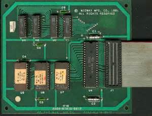
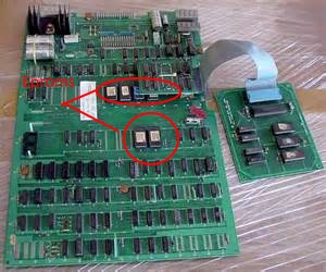
If You give Up and Just want to send your PACMAN BOARDS Off for repair, Try this repair Service Click Here
But, as with all things, this is not always the case.
General note about Pac-man boards: I’ve found that many times the cheap sockets on the boards cause trouble. When I start with a board that is constantly resetting, I usually replace the 28-pin sockets for the 284 and 285 cards with new dual-wipe sockets. Another thing I am now doing regularly is to replace any of the big yellow sockets they used sometimes for the CPU. I’ve noticed when desoldering them, that many of the pins just fall off.
While we are on the subject of sockets and 285/284 cards, DO NOT plug these directly into the socket on the main board, YOU WILL RUIN THE SOCKET. Use another dual-wipe style socket on the pins of the daughter cards, and insert it’s legs into the socket on the board.
Here are some common advanced Problems and solutions I’ve also found around the Web. I have complied them below for your resource:
Problem: strange garbage on the screen
Tools: multi-meter, soldering iron
The game would not get through to initialization sequence. When I went to reseat the Sync Buss Controller, I noticed a gouge out of a trace on the bottom. Testing it with the ohms setting on the multi-meter showed the trace was broken. I jumpering over the broken trace and plugged it back in. The game then powered up and played normally
Solution: Fixed a trace on the Sync Buss Controller
Problem: Missing Blinky from attract screen, Pac-man is invisible, no GAME OVER in red in the middle of the screen. Ghosts appear orangish.
Tools: Soldering iron, solder wick
It took several hours to find, but it turned out the 6 pin 1K resistor network at RM1 had broken legs. It appears to have been bent too many times. When I wiggled the part it would sometimes show all characters and colors correctly. Replacing the part fixed the problem.
Solution: Replaced 1K resistor network RM1
Problem: Pac-man and Ghosts stay only in the top half of screen
Tools: multi-meter, soldering iron, solder wick
It was like the sprites thought the maze was only 1/2 as tall. Pins 12 was stuck high on the 74LS161 at IC 1E.
Solution: Replaced IC 1E a 74LS161.
Problem: Random letters and numbers on the screen
Tools: ABC pac pcb diagnostic module
I was so successful on the repair above with the ABC, that I immediately went back to it for this one. This board went through the RAM tests and passed all diagnostics just fine. So, I knew there was an eprom problem again in ROW 6. I replaced the ROMS and found that I would then get a BAD ROM 0 message in test mode, and the board would not boot in normal/play mode. I reseated ROM 6F and the board worked. Simple fix and easy to find with the ABC Kit.
Solution: Replaced ROW 6 Eproms
Problem: Board constantly resets, but will boot occasionally
Tools: ABC pac pcb diagnostic module, soldering iron, wick and solder
The diagnostics would give me ram errors and would display garbage if I pressed Start 1 to continue. I knew this board would run sometimes so the ram must be good. I pulled the diag board and put back in the Z80. When I tried to boot it back up, nothing on the screen at all. I tried a different Z80 and got some garbage. Pressing down on the CPU allowed the board to boot. Looks like a bad socket. I replace the socket and all was well.
Solution: Replaced 40 pin CPU socket.
Problem: Board works fine in JAMMA adaptor, but dead in a standard AC Pac cab.
Tools: VOM, Soldering iron and solder
The game powered up and played perfectly using a Pac to JAMMA adaptor, but would not power up once it was plugged into the cab. I tested the voltages on the un-banded sides of D7 & D8, this read 15 VAC, then tried the same on the un-banded sides of D3 & D4 reading was 24.56 VAC. Both are fine. Then I checked the DC across the large electrolytic caps C7 & C8, each should read about +5 to +7 VDC. These were fine too. Next step, check the voltage at the Base of the Q6. The reading should be around +7 or so. What? It’s +1.23xxx, Hmm. What is going on? After replacing both Q6 and IR1 I still had the same problem. Just for grins I checked the 5 Watt 50 ohm resistor at R52, since it was the only thing left on that section. Open! The resistor was OPEN! Replaced the resistor and tried the board back in the cab. Powered up a played perfectly. I fixed 2 boards this evening with the exact same symptoms and both had bad R52 resistors.
Solution: Replaced R52, a 5 Watt 50 Ohm wire wound resistor.
Problem: Board works fine in JAMMA adaptor, but kept resetting in a standard AC Pac cab.
Tools: VOM, Soldering iron and solder
After replacing just about every component in the power section with no change, I changed out the large 10,000 uf @ 10V electrolytic caps out of desperation. The board then worked fine.
Solution: Replaced C7 & C8, the two large 10,000 uf @ 10V electrolytic caps.
Problem: Sound would fade out then back in.
Solution: Replaced the audio amplifier, the LM1877.
Problem: Maze area of the screen is white, game still plays
The board ran just fine most of the time, when it was moved, the entire maze area of the screen would turn white, but the top area with the high score and the bottom with the number of credits would stay normal. If I would move the board at all, it would go between normal and the white screen again. Finally the problem was tracked down to the 6 pin resistor pack RM2. Pin 1, leg that is soldered to the power bus, was broken and would intermittently make contact.
Solution: Replaced RM2, a 5x 1K ohm resistor network.
Problem: Music and sound was wrong, missing parts of sounds.
Two resistors were smashed, R2 & R3.
Solution: Replaced R2 & R3.
Problem: Board appears dead, no video, resets constantly.
The board would just constantly reset. Pressing down on the CPU and wiggling the 285 would show just a half dozen or so Zeros on the screen. Replacing both sockets left the board at least showing the zeros *sometimes*. I decided to try a known good eproms set and when I tried to take the 6H and 6J roms out, the socket came with them. I replaced the sockets and put in a known good eproms set, and tried the board again. I came up this time. I reinstalled the original roms and the board still worked, so the problem was bad sockets at 6H & 6J.
Solution: Replaced 4 Sockets for the CPU, 285, 6H and 6J.
Problem: Board show the left half of the screen twice and ran at double speed, sound was double speed too.
This board had been worked on before and had the 74LS161 at 3S replaced. Using a meter I found pin 16 was shorted to the trace that runs next to the chip on the bottom of the board. This trace runs to pin 12 of 2S.
Solution: Removed extra solder that was jumpering pin 16 of 3S to pin 12 of 2S.
Problem: Game would not play. Joystick and coin were not working properly.
I used the ABC Diag board for this one. When I would test the joystick using the board, all 4 directions where toggled at once. Left, right, up and down were all tied together somehow. The LS367 that handles these inputs had already been replaced, but I removed the chip an socketed it. Then tried a new chip. Same result. Well, all the inputs are still stuck together. RM8 might have a problem. I unsoldered RM8 and when I got the first 5 pins unsoldered, that 1/2 of the resistor pack fell out of the board. Ok, so it’s broken in half. Replacing RM8 with a new 1K x 9 resistor pack fix the problem.
Solution: Replaced bad resistor pack RM8
Problem: Dead board. Plays but no video.
Solution: Bad LS20 at 3E
Problem: Garbled sound, really tinny.
Let me first say, I hate working on sound problems on Pac boards. Seems I always end up replacing the entire sound section and still get the same results. This board was no different. I first tried replacing the rams at 2L & 2K, no change. Next I tried replacing the 74LS174 at 1L, no changes. Next I replaced the 4066 at 1N, no change. On to the 74LS283 at 1K, no change. On to the 74LS273 at 2M, no change. What!!?!?! Ok, let’s look at 4F. Pin 8 of the LS86 at 4F should be pulsing, but it’s stuck high. This pin feeds pin 5 on both the LS157 at 3L and the LS158 a 3K which then feed the data to the sound rams at 2L, 2K. I socketed this chip and still, no change. Then it dawned on me. There is a tiny little glass capacitor that goes between pin 8 and ground before it connects to the other pins. I unsoldered the cap and had sound! This cap was way too large. I replaced it with a 220 pf ceramic. I had sound now, but it was like all the bass was missing. I noticed that if I pressed on the board around the sound section I would get nice sound, but only briefly. Looking at the schematics I started checking the work I did earlier around 2M. Checking each pin with a meter and checking
where they were supposed to be connected. Doing this on pin 11 to R9 showed open. I jumpered the connection on the back of the board and fired it up. Sound was perfect then. So it seems I had broken the trace when I socketed that chip.
Solution: Replaced wrong value capacitor C34 with the correct 220 pf cap, and fixed a broken trace between pin 11 on 2M and R9.
Problem: Messed up maze.
Solution: replaced bad socket on the 284 card at 5S
Problem: Dead board
The crystal was oscillating, but the 74LS161 at 9C, pin 15 was chirping, meaning the watchdog was resetting the cpu every second or so. Probing pin 26 of the Z80 showed it was floating, it wasn’t high and it wasn’t low, the logic probe didn’t light up at all. This board had one of the large yellow 40 sockets for the CPU. Removing the top of the socket, it appeared the pins were not making contact so I replace the socket. No change. Next I traced back pin 26 to the 74LS02 pin 13 at 7L for continuity. The trace was fine. I powered up the board and probed pin 13 of the LS02, it too was floating. Checking the inputs of the chip, the were both OK. Replacing the chip fixed the board.
Solution: Replaced the 74LS02 with floating output on pin 13 at 7C
Problem: no sound
I check the sound amp by running my finger over the solder side pins. Usually this will result in static, but it was silent. I replaced the LM1377 sound amp and the sound was fixed.
Solution: Replaced faulty LM1377 sound amp at 11A
Problem: Squished picture horizontally, board runs super fast
This was an interesting fix for me, because I used a tool I had never used on a Pac-man board before. I built a video probe that displays data on the monitor. A video probe is a wire with a 470 ohm resistor on one end and an alligator clip on the other. The bare end of the resistor is the probe and the alligator clip is clipped to one of the color outputs of the board.
First, I used my logic probe to check the outputs of pins 11, 12, 13 and 14 of the 74LS161 chips at 2R and 2S thinking that an output was sticking. They appeared to all be doing their job because all the pins were pulsing. This had me puzzled, I expected that either 2S or 2R were faulty because they generate the timing signals used to draw the display horizontally, but they appeared to be fine.
I had just been doing some Galaxian repairs and had built a video probe to help troubleshoot a problem with a Galaxian board. So I thought I’d give it a shot on this board. I clipped it on the output side of R33, then probed the outputs of 2R, 2S again. What should I should have seen, when I moved from the lower number pins to the higher number pins, is the number of vertical bars display on the screen double. When I moved to pin 12 or 2S, there was no bars on the video display at all . The output of the 74LS161 at 2R, pin 12 was wrong. Changing the chip fixed the board. How the chip failed in this way, I don’t know. Generally they fail by an output getting stuck high or low.
Solution: Replace the faulty 74LS161 at 2R
Problem: Entire playfield was covered in horizontal red lines.
Game would play, but you could not see the center maze section below the High Score section and the CREDIT section at the bottom. Using a jumper, I checked each 2125 ram at 2A thru 2D and found that the only one that effected the screen when jumpered high or low was 2D. Replacing that ram fixed the board.
Solution: Replaced 2125 RAM at 2D.
Problem: Speckles are sparsely spread on the screen when the board is running in various colors all seem to be the same color at the same time. Looks like noise of some kind.
Figuring it was a ram problem of some kind, I piggy backed a chip on each of the 7489s at 3F and 3H. The problem cleared up! Removing one piggybacked ram at a time revealed that the problem was with the ram at 3F. Replaced the 7489 and the problem was gone.
Solution: Replace faulty 7489 RAM at 3F.
Problem: Constant loud thumping sound. Volume control has no effect
Solution: Electrolytic Capacitor C51 was open, 330uf @ 16V
Problem: Tinny sound
Solution: Replaced bad LS273 at 2M
Problem: Tinny sound
Solution: Replaced bad sockets for sound proms 1M and 3M
Problem: All characters stuck at the top of maze
Solution: Replaced bad LS161 at 2E
Problem: White screen, no characters or maze. Game plays, sound is fine
Solution: Replaced bad 82S23 at 7F.
Problem: Tinny sound
Solution: Replaced bad cap C1 .01 uF 50V cap
Problem: Dead board
The board was getting no power to any of the +5 rails. Since my test bench is using a JAMMA setup, I jumpered from one rail to the +5V side of D8 and the board ran. Testing the voltage output at Q6 showed there was no power getting through it. Replacing the part fixed the board.
Solution: Replaced bad Q6 (TIP31A)
Problem: Sprites jump in all directions, but not all the time.
This was an interesting problem. This board had 2 ghosts and pac that were fine until Pac ate a power-up. As soon as you ate the power-up (Power pill) the ghosts would turn blue and all would then have the same jerky behavior. It happens in all directions. This turned out to be pin 14 out of circuit (broken trace) to on the 7489 RAM at 3H
Solution: Fix trace from pin 14 on 7489 @ 3H to 16 on the 2114 at 4K.
Problem: Board was dead, power problem
Testing the power on the power rails on the logic section of the board showed only about 2.15 Volts on the +5 line to all the chips. I tested the voltage across C6 & C7 expecting it to be low also, but it was a steady +5. Moving on the the D44VM4 @ Q6 (big transistor with a heat sink) showed that the center pin (collector) was getting +5, but both the emitter and base were only reading 2.15. If I jumpered from the + side of C7 to any power rail, the board would boot. Replacing the D44VM4 with a TIP31A fixed the board.
Solution: Bad D44VM4, replaced with new TIP31A
Problem: Board would occasionally boot, watchdog going nuts
It would sometimes run the Two-Bit ABC Diag board with no trouble at all. Other times it would reset, other times I’d get BAD V RAM 0. I replaced just about every socket on this board, and still had the same problem. Pressing near the prom at 7F would occasionally make the board boot, but if you let go, it would again reset. I started looking at the LS367s in row 8. Piggy-backing them one at a time, when I got to the chip at 8D, the game booted and stayed running. Replacing the chip finished the repair. What a long way to go to find the culprit, but at least this Pac now has all new sockets and should run just dandy for quite a while.
Solution: Replaced faulty LS367 at 8D
Basic Pac-man Board Tips
All Ms Pac Man printed circuit boards are actually Pac Man circuit boards that have had a auxiliary board plugged into the original location of the Z80 CPU and the 2 character chips at 5E, 5F changed to Ms Pac chips.
- First troubleshooting tip for Ms. Pac boards is to remove the ribbon cable/auxiliary board from the main PCB and then transfer or better yet install a known good Z80 into the CPU socket. If the Ms. Pac-man now runs but exhibits odd characters you know that either the ribbon cable or some component on the auxiliary board is deffective. (The card can be eliminated, read on….)
- Check the piggyback boards at 5S and 6D to be securely seated. (More on the Piggyback Boards)
- Check dip switch #8 to be OFF
- Check slam switch on coin door to be normally open.
- Cocktail boards are identical to uprights, to enable cocktail mode edge connector pin R is grounded.
Pac-man Board is Dead
No Sync, no Clock.
Replace 74LS74 @ 8C.
Signs of Life
No Vertical Sync – lines and colored block out of sync. No game play.
Replace 2R & 2S (74LS161)
Red Screen on Maze portion only, HI Score & Credits legible
Short on Ram Chip @ 2D.
HI Score & Credits legible, no Maze or graphics. Shorting 3E pin 6 to pin 7 shows maze but no sprites.
Bad 93415 RAM pulling Chips Select down.
6 Moving blocks of scrambled garbage
Replace 74LS74 @ 3N, output pins 5 & 6 bad.
Flashing A in upper right & Flashing “2” in Lower left
Pin 1 of 6H out of socket
2-3 Characters in upper left – seems locked up
Check 74LS74 @ 8C for lifted pin 11 used in speed up mods
Maze has white bar running top to bottom. Maze is okay but has sections of white instead of blue. “TOP SCORE” & other letters change color on demo screen as new characters enter.
Replace 2114 Rams & check sockets.
Powers Up but as characters come on screen it resets.
Bootleg Ms Pac – Rom 5 is Bad.
Checkerboard / Picnic Table pattern, Test Grid looks like “L”s
74LS139 @ 5C outputs 9, 11, 12 bad.
Seems locked up but will occasionally start if you keep toggling it off and on. Reset button on board will not work.
Replace 74LS161 @ 9C.
Game resets often, and/or won’t boot. (Also causes Clay’s Multi-Pac to reset to menu and freeze)
Chip 8B, 74LS368, inspect for cold solder joints or corrosion on pins. (Thanks Jeff)
Constant Reset, Shorting Z80 pin 34 to pin 35 will force boot but with corrupt graphics. (PAC 3 board)
2114 Ram at 4M bad (4P on real board).
Game will only run with custom Sync Bus Controller chip, not with TTL equivalent.
74LS161 @ 3R has poor connection pin 7, effects 2H signal.
Horizontal white lines, can see Marquee lights on intro screen & can see “trail” of Ms Pac in Maze.
74LS174 @ 1H pin 9 open.
Garbage, RAM test dies at $4080, AB7 appears good.
74LS138 @ 7J interfering with good reads from RAMs. (3/24/02)
Plays But….
Plays, Garbage on screen…. U H S A T B T O (push button to play text)
Replace V-ram address board ( 284)
Plays, 4 Ghost & Pac Man in Maze.
Replace 74LS20 @ 3E (bad output).
Plays, Images and Text are 4 1/4 of the left side of a Sprite repeated.
Bad 74LS283 @ 1F (pins 9, 10, 13).
Plays, Images are 4 1/4 of the left side of a Sprite repeated. Placed slightly to left of Marquee box (Ms Pac). Motion & Demo are jerky.
Bad 74LS283 @ 1E (pins 1, 9, 10).
Plays, but Text (GAME OVER) is split in half horizontally & wrapped around.
74LS86 @ 4E, pin 5 bad.
Plays, 2 parts of moving objects.
Replace 74LS283 @ 2F (bad output).
Plays, but moving objects are 2 copies of left half.
Replace 74LS157 @ 4D (4E), pin 7 bad.
Plays, 2 copies of moving Sprites on Attract Screen, MS Pac is 2 halves, (Red, Blue Orange Ghost are halves too before game starts).
Bad 74LS283 @ 2F (pin 10 high only).
Plays, Green running dashed lines on the screen otherwise okay.
Replace 74LS75 @ 3D.
Plays but screen is covered with white “snow”. Heat related, not Video RAMs (2A~2D), Character ROMs or Scratchpad RAMs (4K~4R).
Replaced 74LS75 @ 3D.
Plays but Constant Chattering/ Static Noise, Sprites are corrupt. Maze has 2-3 bands of erratic displays.
Bad output on pins 5, 6 of 74LS74 @ U4 of Sync Bus Controller.
Plays, Men & Pac Man too high in Maze by 2-3 Characters
Pins on Ram @ 2A shorted to each other.
Plays, Pac Man too high in Maze, jumps about vertically.
74LS161 @ 2E bad outputs. (Thanks Chuck)
Plays, Double Vision, 2 mazes side by side.
Replace 74LS74 @ 5M, no output on pin 9
Plays, Characters are odd blobs in game but correct on demo screen static pictures Also motion is wrong – demo screen characters move diagonally
Pin 8 of 5S (Vertical Ram Addresser 284) is out of socket
Plays, MS Pac running light marquee is numbers & Midway Logo is parts of Speedy.
Roms 5E & 5F are Pac Man not Ms Pac Man Roms.
Plays, but graphics colors are wrong.
Bipolar Proms at 4A & 7F are wrong/bad (see check sums page).
Plays, but Orange Pac-Man on the playfield and the cyan/pink ghosts.
Replace 2A 93415 RAM. (from RGVAC newsgroup).
Plays, But Sue runs out of maze & erratically jumps about.
Replace Rom @ 6F (Speed-Up Bad).
Plays, But sync needs to be readjusted and bottom of maze is off screen, under the credit display.
Replace 74LS161 @ 3S (Signature shows problem).
Plays, But speed & sound erratically change & game may occassionaly crash.
Bad 74LS249 @ 9N (bootleg board).
Plays, But all moving characters are at the bottom of the screen moving left/right only.
Replace 74LS377 @ 4B. (Output pin 6 was bad)
Plays, But all character movements horizontally (left/right & vice versa) are jerky (Vertically okay).
Pin 15 @ 1F (74LS283) out of circuit.
Plays, But Vertical “Hum Bar” (Scrolling black/dark line on monitor about 1 inch wide.)
See the Vertical Bam Hum area under the Power Supply section.
Plays, No Characters in Maze or intro Screen. Dots visible & disappear as eaten.
(rare case) Dead 74LS157 at U5 of V-Ram Addresser (rare case).
Plays, 2 Sets of Characters in Maze, Large blank stripe down the left side of the screen from top to bottom, Characters in wrong places but dots disappear correctly.
64V missing from 2F 74LS283 pin 14.
Plays, But Maze graphics are wrong/ corrupt. Full of large segment of “super Pac Man” from intermission.
No HBLANK signal to pin 4 of 74LS174 @ 1H. (Traced back from graphics roms chip selects)
Plays, But Ghost, Maze & Pac are Corrupt.
4D pin 2 bad.
Plays, But corrupt graphics blocks (See http://www.seanet.com/~wilson/arcade/pacman.html)
Replaced 74LS174 @ 1H.
Plays but No Red on moving sprites (Ms Pac Bow/ Cherry/ Speedy).
Ram Data Bus D5 high resistance.
Plays, But Maze graphics from the bottom half are displayed on the top half also. Characters follow the original maze patterns.
Replaced 74LS257 @ U2 on VRam addresser board
Coins up but joystick only moves Pac-Man down. Rack Advance (dip switch 7) doesn’t work.
Pin 15 of 8E is out of circuit
Plays, but Pac/Ms. Pac and all the monsters go through the maze upside-down! All other graphics are okay. Pac and the monsters look like they’re upside down.
Bad 74LS157 at location 4E, pin 9. This chip is a quad, dual-input multiplexer. The “FLIP” signal, activated when the board is in cocktail mode, flips over all video signals during Player Two and this chip was not selecting its inputs correctly. “FLIP” was getting through in this channel when it should not have been. Replacing this chip cured the problem.
Other Specific Problems + Fixes
Plays, but monsters look like they’ve had a labotomy – heads cut off
RA3 output from 1E pin 11 goes in a chain sequentially to pin 9 at D1, C1, B1, A1 and then over to pin 13 at 2A, 2B, 2C and 2D. The problem shown in the photo was caused by an open between 2B and 2C such that 2C and 2D did not get the input. Ran a jumper to complete the chain to solve the problem.
Z80 Sync Bus Controller
It is easier to troubleshoot a known bad Z80 Sync Bus Controller (Z80 SBC) in a known good board than to find it on a unknown board. These piggyback boards are often installed backwards & powered up, frying them. If you don’t have piggyback board on an original board or simply want new replacements see 284, 285 Custom Chips below.
Piggyback Socket
Both the SBC & the other piggyback board (V-Ram Addresser) have 2 small holes that nylon ‘zip ties’ are threaded thru & looped under the main PCB to hold the piggyback boards in place. This does not allways ensure that the board is sitting square & flush as the piggyback boards have some mobility despite the ‘zip ties’. This will also conceal broken pins that can occur on the male socket of the piggyback board . It is not uncommon to see the ‘zip tie’ and the socket removed from the piggyback board which is then reinserted into the main PCB socket (female end) at 6S/5D. This is a “one time fix” as the PCB socket is expaned to accomodate the large square pins of the naked piggyback board. At this point the you will need to replace both the socket on the main PCB & the socket that is on the male end of the piggyback board. You will need to use a Double Wipe Tin Lead 28 pin socket, a machine pin socket will work for the main PCB but not on the piggyback boards.
U0 74LS139 if this fails the symptom will be the static garbage on screen. You can quickly diagnose this failure with a logic probe. Be sure that you have pulsing activity (full range high to low) on the input pins 3, 16 & 27 of the Z80 SBC (the 28 pins that connect the SBC to the main circuit board). Next check for ouput at pin 17. (You may want to look for pulsing at pins 10 & 12 of the 74LS139 also).
Pins 12 & 13 of the Z80 SBC are outputs of the timing section. Lack of activity at these pins could indicate problems after the 74LS139.(U1, U2 & U4)
U5 74LS244 is the buffer between the Z80 and the circuit board on the eight data lines. U5 only buffers data that flows from the Z80 to the board and is enabled by the output pin 9 of the 74LS74 at U2.
Symptoms of U5 failure vary. 74LS244’s often will exhibit “noisey” or eradict outputs on a single line. Visually in Pac-Man this can vary from No Text on Intro Screen to Eradict Operation / Intermittent Crashes. The symptoms may be thermal related, becoming more frequent with time/ heat.
Diagnosing this is beyond the ability of a logic probe in most cases unless the outputs are stuck high or low. An Oscilloscope may help to spot “noise” or lines that fail to swing beyond the marginal range of TTL signals (0.8 to 2 V for 74LS244’s).
V-Ram Addresser
The V-Ram Addresser is not plauged by being plugged in backwards as often as the Sync Bus due to it’s size & the fact that it sits offset of the PCB if plugged in rotated 180′ from normal.
Be sure to read the note about piggyback boards & sockets in the Sync Bus Controller section above.
Pin 11 of the 28 pin socket connector is sometimes used as a point to attach speed up kits. Inspect this pin for excess solder shorting to the adjacent trace or pin.
Plays, No Characters in Maze or intro Screen. Dots visible & disappear as eaten.
(rare case) Dead 74LS157 at U5 of V-Ram Addresser (rare case).
Plays, Screen Full of “F”‘s on power-up. Intro screen full of red “1”‘s.
74LS257 at U3 pin 3 out of circuit.
Plays, But Maze graphics from the bottom half are displayed on the top half also. Characters follow the original maze patterns.
Replaced 74LS257 @ U2 on VRam addresser board
PCB Power Supply
If you have a wavy picture, no blown fuses, and the filter caps of the power supply are connected securely, the problem is most likely a poor ground. Remove the yellow ground strap from the transformer mount and screw it to the metal case of the line filter. (“Frank the Crank” PlayMeter 8/15/85)
You need to troubleshoot the power supply section when
- your PCB does not have +5 VDC as measured across capcitors C2 or C3 (easy to get to).
- your games has no audio and you must first verify that there is +16 VDC for the audio amplifer.
- your game plays, but vertical “Hum Bar” (scrolling black/dark line on monitor about 1 inch wide).
Power the game OFF. Check all 4 fuses grouped together in the bottom of the cabinet (from the back door). To check the fuses remove them from the fuse holder (one at a time as not to mix up the different sizes) and Ohm them out using a multi meter. Visual inspection may not be good enough, using a multimeter to ensure that you have a good fuse is worth the extra minute.
Inspect the fuse holder as you check each fuse. The fuse holder must be clean and hold the fuse tightly, making a good connection. Replacing the fuse block is not a bad idea and may be necessary if you have a weak/ broken holder (see the Vertical Hum section).
Next inspect the edge connector & harness. You may have a RF filter board inserted between your main circuit board & harness. The RF filter board was meant to reduce radio frequency interferance caused by the Pac-Man game. Most operators have long discarded these filters since they cause more power supply connector problems and the RF interferance is not a problem.
You are looking for connections that are blackend or burnt. The fingers inside of the plug connector may have lost their spring and will not make a good connection to the PCB when inserted. Replace the edge connector if you find evidence of either situation.
To double check your inspection/ repair work so far, reconnect the board and harness & power on the game. Using the AC voltage setting of your Multi Meter measure the voltage from D7, unbanded side to D8 unbanded side. If all is well you should read about 14 Volts AC. A reading of near 7 Volts AC would indicate that one half of the AC voltage path is still faulty. Recheck fuses, fuse holders, and connectors to find the culprit.
Next measure the AC voltage from D3, unbanded side to D4 unbanded side. We are looking for about 25 Volts AC. A reading near 12 Volts AC would indicate that only half of the AC voltage path is working. Recheck fuses, fuse holders and connectors to find the problem.
NOTE the very last run of Ms Pac-Man cabinets did not use the normal AC tranformer setup as described above but used a latter MCR style transformer which is a much larger silver metal box with a Black transformer, large cylinder capacitors & Molex plug connectors. This particular setup does not supply AC to the Ms. Pac-Man board but DC voltages.
Next read DC voltage from ground to the top end of R52, about 12 Volts DC. Missing voltage here would indicate open R52.
Next read DC voltage from ground to BASE of transistor on Heat Sink, should be about 5 VDC.
Low Voltage 2~3 VDC when measured at C2 or C3. Resistor R53 4 Ohm 10 Watt gets warm. Measured Voltage from Ground to the Base pin of Q6 ( D44MV4 on the big heat sink, may also be a TIP 31 or ECG 377) Shows ~ 8 VDC.
Replace D44VM4. Be sure to install mica insulation & plastic sleeve on the the bolt too.
~ Note the pins on Q6 are marked on the board or refering to the above picture top to bottom
B) ase
C) ollector
E) mitter
Plays, But Vertical”Hum Bar”
Scrolling black/dark line on monitor about 1 inch wide.)
If you want to fix it one time & forget it, then change the 4 block fuse holder & Scotch-Brite the fuse ends. Next, get a Molex 22/44 edge connector with split pins (same as Jamma) and cut the wires about a ¼” up from the old never was a connector, one at a time & transfer them into the same positions in the Molex edge connector.
Solid Pac for a lifetime…..forget the caps on the pcb other than resoldering C6 & C7, as these sometimes have a cold soldered leg, about 2 percent of cases, but nevertheless a possibility.
When one of my ops has a Pac series trouble, you can bet it is on-board, because Molex keeps on ticking & the newer heavier fuse blocks last & last, unlike the flimsy ones originally installed.
Check Zener diode D9. I’ve seen this diode go bad & shunt 5 volts to ground, even seen the game over fused and the diode heat up enough to be removed without a soldering iron.
IR1 is a voltage regulator.
Pac to JAMMA
Interesting “For Your Information” Content about Pac-man
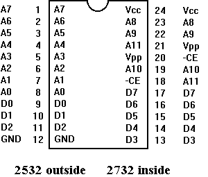
2732 Retrofit
- 6E – Tie pin 18 to Ground, Tie pin 21 to A11 @ test point edge connector
- 5E – Tie pin 18 to Ground, Tie pin 21 to 4D pin 2
*Note this is for the pins lifted from the socket, to use the original socket would require you cut the original traces at pin 18 & 21 to isolate them first.
255 Split Screen
Split screen is true at screen 243 on Pac Man, Ms Pac just resets. This can be seen using the rack advance dip switch at 16 racks per minute for about 15 minutes.
myself & fellow Tech John Robertson in the past but we never had been able to repeat it or isolate it until a crafty programer/ hacker David Widel helped out.
This piece of code is found in the original Midway Pac-Man ROMs @ $3289. Place the game in the test grid screen (Monitor Convergence screen) by switching test mode on then quickly jiggling the test switch out & back into test. Next move the joystick
13 = $0U16
ROMS & EPROMS
Almost all original Pac man boards used masked Roms (9332Bs) that are black, some of the latter Ms Pac Mans had eproms (2532s) with white paper stickers over the windows. The pinouts of the 9332B and 2532 are compatible.
To identify rom chips read the top line of print….”0072-M932D-”
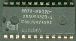
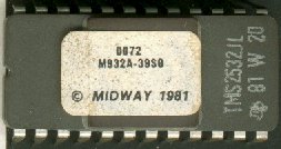
- M932A-39S0 = 6E
- M932B-39S0 = 6F
- M932C-39S0 = 6H
- M932D-39S0 = 6J
- M932E- = 5E
- M932F- = 5F
Note that the letter after 932 is the position indicator.
I am not sure of how to read the second line but you will notice the 9332B, which is a reference to the format of this chip. The 9332 is the equivalent of a 2532.
The second chip (right side) is a EPROM.
Third line is the MIDWAY Copyright (1981) for most Pac Man games (though it was introduced in 1980).
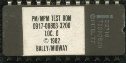
I purchased this ROM from the net. This is for the Midway Test Fixture. (Where to buy a Pacman Speed Up click here)
Color PROMS
 There are 2 color proms that dictate the final color of the maze and character. Pac Man & Ms Pac use the same color proms, other games may vary (see “How many games run on the Pac Man board?).
- 4A PM 1-4 – 256 x 4 PROM (82S126N, 1M 5623, 63S141) Tri State 82S129N will work.
- 7F PM1-1 – 32 x 8 PROM (82S123N, 7603)
Note that these color Proms are only half full of data which is normal and allows for a switchable design if you wanted to make new color proms & toggle the highest address line manually (Clay used this approach on his hack).
To patch color PROM 7F load & burn data at $10 then cut split pad open above 7F.
To patch color PROM 4A load & burn data at $80 then cut split pad to right of 4A (don’t solder shut).
RAMs, Video RAMs
2114 @ 4K ~ 4R
4K (low bits), 4N (high bits) are Character Data $4000 – $43FF
4L (low), 4P (high) are Color Data $4400 – $47FF
4M (low), 4R (high) are Scratch Data $4C00 – $4FFF
93415 @ 2A ~ 2D
Replacements may be
2115 or
2125 (intel)
B.G. Micro (www.bgmicro.com)
Part # ICS212570 (2125A-2 1Kx1 70NS) Thanks Andy
7489 or 82S25 @ 2K, 2L & 3F, 3H
2K, 2L are part of the sound section.
3F, 3H are part of the video output section.
plier Board does just that, it takes a single coin switch input & multiplies it by a factor set by dip switches. The credit multiplier board is mounted inside the back cabinet opposite the main PCB. I’ve never seen an actual credit multiplier PCB and assume that it was for non USA games?
In place of a credit multiplier is a Credit Multiplier Bypass board, a small PCB with a single row of Molex header pins that plugs into the harness. The schematics of a credit multiplier are show in a Pac-Man manual. Notice also that any cabinet wired for a credit multiplier board installation will have 2 coin meters, not one.
WHERE TO FIND MULTI PAC PCB BOARDS like Super ABC KIT and Multi Pac-Kits
Light Bulbs
Mini Marquee
194 Bulbs 14V wedge (5 needed)
Cocktail Table
194 Bulbs 14V wedge (4 needed)
Cocktail tables have a different transformer with a seperate fuse for the coin door lights, 1 1/2 amp slow blow.
Coin Doors
1895 Bulbs 12V Bayonet (1 or 2 needed)
Florescent Marquee
18″ Cool White (18TCW)
Starter ?
A cheapie “under the counter” style florescent fixture from you local hardware may be an easier fix than replacing ballast.
Pac-man Cabinet Dimensions
Upright
Height 73 inches
Width 26.5 inches
Depth 24 inches
Weight ?
Mini (Caberet)
Height 60.25 inches
Width 19.5 inches
Depth 24 inches
Weight ?
Cocktail
Height 29 inches
Width 32 inches
Depth 22 inches
Weight ?
Counter Top
Yep there was actually 1 prototype that showed up on E-bay in 2001. It was an attempt to pitch selling home machines through high end catalog stores that never came together.
Paint / Cabinet Restorations
Ms Pac-Man Blue
Dutch Boy color “Pacifica” (2-B-4) is a perfect match.
- Glidden – Passion Flower – 30RR 26/335 (Blue)
- Glidden – Rhapsody – 50BG 61/306 (Pink)
- Glidden – Sunny Side Up – 37Y 61/877 (Yellow)
I used a flat color and am going to protect it with a gloss, but you have the option for flat or gloss….I think if I did it again, I would try.
Replacement T-Moulding
Orange Replacement T-Moulding to match the original Pac-Man color is available from T-molding.com
25 feet will leave you a bit to spare on a dedicated pac-Man.
Tools: Rubber Mallet (or some no mar hammer device), Screwdriver, Knife or shears.
To remove the old T moulding simply take a screwdriver & pry free the old moulding from one end top back or bottom front).
Pull the old moulding out by pulling directly back in the same plane as the cabinet side (in other words don’t try to pull the old moulding at an angle so that you could crack or break your cabinet, with plywood Pac-Man cabinets this shouldn’t be an issue but with particle board it may be).
Once you remove both pieces you may notice that some spots the insert part of the original moulding was cut out. This is done to allow the T moulding to bend to a tight radius curve. You will need to duplicate these cuts as you install the new moulding.
Begin by inspecting your groove and ensure it is clean & clear of debris. Place the new T-moulding in the grove starting at the bottom. At the first corner rising up the front of the machine by the cash box you will need to notch the rib. A “V” shaped notch or even a bit wider is okay. You want to remove enough of the rib to make the curve fit tight into the groove but no more than needed.
Continue to work your way up the face of the cash box area, seating the moulding with your mallet as you go.
The tight curve at the Control panel will require another notch similar tothe first. The top front & top back will also require notches.
Some operators prefer to nail the ends of the T-moulding in place. This should not be necessary as long as the groove was clean & the rib fit snuggly.
Ribbon Cables for Ms Pac Man & other Auxilary Boards
These are pretty easy to make…
Order at least two of part #42712 (.100″ IDC Flat Cable Plug, 40 pin – Originally part #42711, but discontinued) from Jameco (800-831-4242). Crimp them onto a 40 pin ribbon cable (a piece of IDE hard drive cable will work fine) and you’re ready to go. You can use a pair of pliers to do the crimping, although the “73251” (IDC Crimping Tool) will a better job for $15. Order more than two of the connectors (even if you only need two) ’cause you might mess up the first one you try…
If you’ll even need to make more than a couple ribbon cables the investment in the tool will save you time and $$$ in the long run.
FAOQ (Frequently Asked Other Questions, ones that haven’t been covered yet)
Can I run Super Pac Man on a Pac Man PCB?
No, Super Pac Man is a 6809 based game & will not run on a Z80 based system.
Can I run Jr Pac Man on a Pac Man PCB?
No, not yet but it may be possible. I have parts of a board that supposedly did this. I have not proven it to work, but I cann’t prove it impossible either!
Can I run Baby Pac Man on a Pac Man PCB?
Well what about the pinball parts? Completely different system here.
How can I tell if my board is bootleg or original?
All Midway boards will have the “Midway MFG. CO” and other identifying marks in the etched into the printed circuit board in the middle section, you cann’t miss it. Bootleg boards are often times smaller & run on DC voltages thus have no large heat sink & huge capacitors like the original board.
On my Ms Pac Man, when I power up the game the coin meter (counter) clicks 2 times, Why?
You have a bootleg conversion and not the original auxiliary board conversion. Does Clay’s kit do this?
Can I take a transformer (panel/wiring harness) from an upright & place it in a cocktail table?
Yes, But the transformer in the cocktail table has an additional set of 12 VAC taps on the Isolation transformer for the “extra” lights over the control panels.
284, 285 Custom Chips
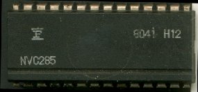
Originally the two sockets 5S and 6D were to house 28 pin custom chips but high demand & production problems forced Midway to manufacture the two piggyback boards using discrete TTL chips. Unfortunately these piggyback boards are often destroyed or simply missing in action. The custom chip pictured above is from 6D. 5S would have a NVC284 chip, which appears to be even rare than the NVC285. The custom chip (6D) is handy for troubleshooting as it allows easy access to the CPU pins.It is also possible to find this chip (NVC285) on Rally X boards.
Return Home
Looking for hard to find Pac/Ms Pac parts for your game? Click here for our Parts for Repair Page



i think these are the only Zeebo in the US, is a retro emulation console too ? http://www.ebay.com/itm/Zeebo-Console-Complete-TecToy-Brazil-Good-Condition-USA-SELLER-/131916308145?hash=item1eb6d31eb1:g:PlkAAOSwMtxXukY2
http://mikesarcade.com/arcade/repairs/mspacman.html